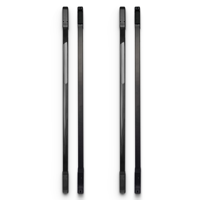
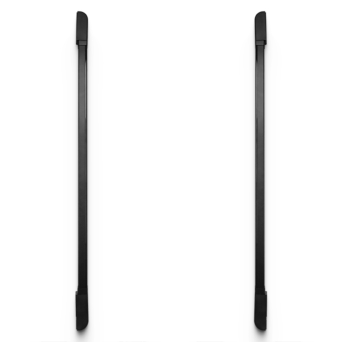
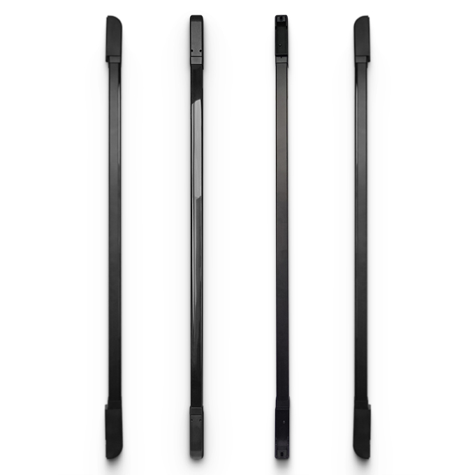

Description Of The Product
- The PB10-8L15 series safety device is composed of N transmitter units and receiver units, both contained within sturdy aluminum profles. Beams of infrared rays are generated capable of detecting the presence of people and / or objects when interrupted. The communication between the transmitter unit and the receiver unit is carried out optically and, therefore, no electrical connection between the two units is necessary.
- To avoid reflections and / or reception errors, a unique identifcation code is set for each infrared beam. When an object, limb or body of a person interrupts the beam of rays emitted by the transmission unit, the output is immediately opened by the receiver unit, with consequent blocking of the automation. The system is only safe when the TEST system is used, this allows you to check the correct functioning of the barrier .
- Typical applications of the system include detection of people or material obstacles near access gates such as: 1.High-speed folding doors and sectional doors, 2.Sliding doors and gates.
Products Parameter
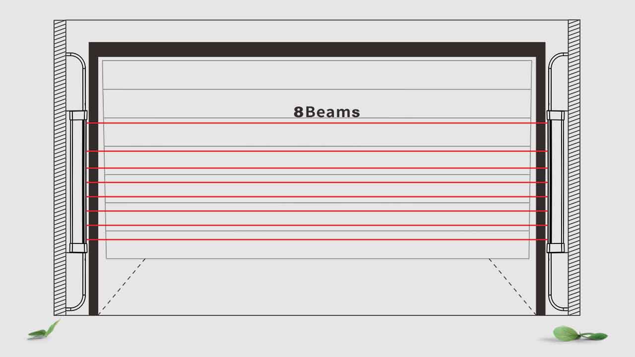
| Number of Beams | 8 |
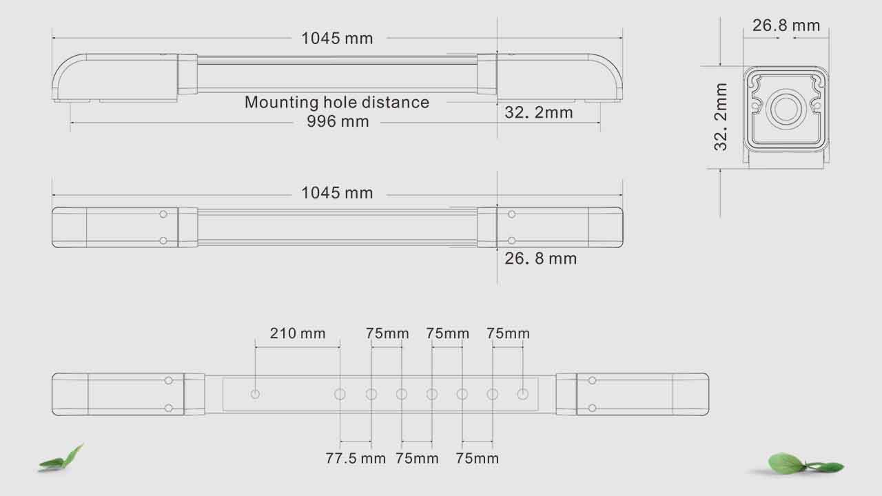
| Height | 1045 mm |
| Detection Distance | 15m |
| Working Voltage | DC12-24V |
| Transmitter Operating Current | <50mA |
| Receiver Operation Current | <50mA |
| Response Time | 50/100/150/200ms adjustable |
| Trigger Time | Block a beam of light, trigger in 2 seconds, block adjacent 2 beams or more, trigger immediately |
| Induction Method | Single beam trigger or Multi-beam trigger(can selected) |
| Working Temperature | -20~60℃ |
| Ambient Temperature | 90%RH In Max;(No condensation) |
| Alarm Output | Wired Output, relayOutput30VDC@2A,125VAC@1A |
| Output Way(Wired Model) | Wired transmission,(NO/NC) |
| Rotation Angle | 180 degrees horizontal |
| IP level | IP65 |
| Material | Aluminum Alloy And PC Plastic |
Products Size Photo
Curtain Photocell Installation
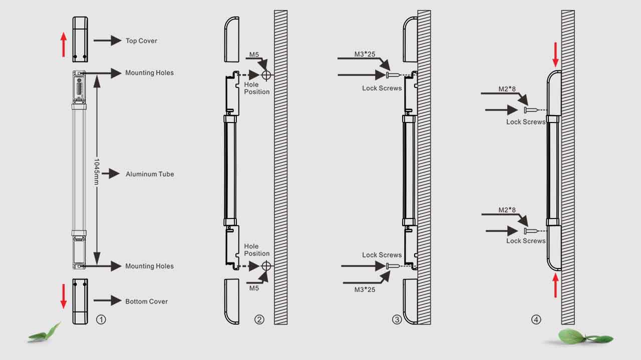
Operation Step
♦ Remove the Top and Bottom Cover,and connect the wires,and lead the thread end from the threaded port.
♦ Confirming the installation position , align the transmitter and receiver in parallel, and mark the hole positions.
♦ Use a percussion drill to drill holes at the location of the wall marking hole, and knock the wall plug into the fixing hole to fix it with screws.
♦ Use M3*25 screws to lock the transmitter and receiver, and connect the power supply to test. If the angle is deviated, you can rotate the aluminum tube for correction. After debugging, lock the rotating screw.
♦ Using M2*8 Screws locked top cover and bottom cover , and testing.
Connection Details
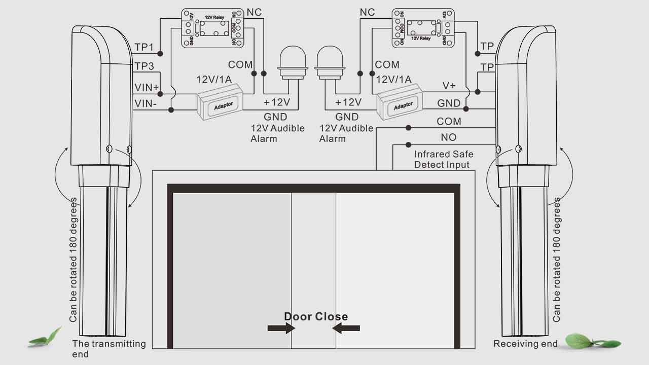
Application Layout
Product Operation Status And Troubleshooting
| LED Indicator status( connected power) | |
| launcher | Green LED is on, Transmitter power supply is normal |
| Receiver | Warn: Green LED is on, the red light goes out, no sound prompt |
| Alarm: Green LED is on, red LED is red, have a prompt | |
| Phenomenon | Probable cause | Processing method |
| Connected power, The LED indicator not bright | 1.The positive and negative poles of the power cord are reversed | Check the positive and negative anodes power line, correct way connection the power line |
| 2.The power voltage abnormality | Measure whether the access voltage is within the range | |
| 3.The power cable is short or disconnected | Check the cable routing | |
| Alarm or false alarm all the time | 1.Misalignment of eyes | Rerotate and aim at the eyes |
| 2.The installation distance is greater than the receiving distance | Re-adjust the installation distance and less than the receiving distance | |
| 3.The installation position is unstable and shakes | Reinstall and fix it, making sure it will not shake | |
| 4.The power voltage not stable | Change the stable power supply | |
| 5.Dip settings and the photocell eyes number are correct | Check the Dip setting, make sure the correct number of the photocell beam eyes | |
| Not alarm | 1.Detection object does not block the photocell beam | Detection object cover the two eyes photocell beam or more |
| 2.The single photocell beam block not enough timephotocell beam or more | If use the single photocell beam, the single photocell beam block time need 2 seconds or more time | |
| 3.Reflection interference | Remove reflective object or adjust the eyes direction | |
| 4.The signal line is open circuit | Check the signal line |