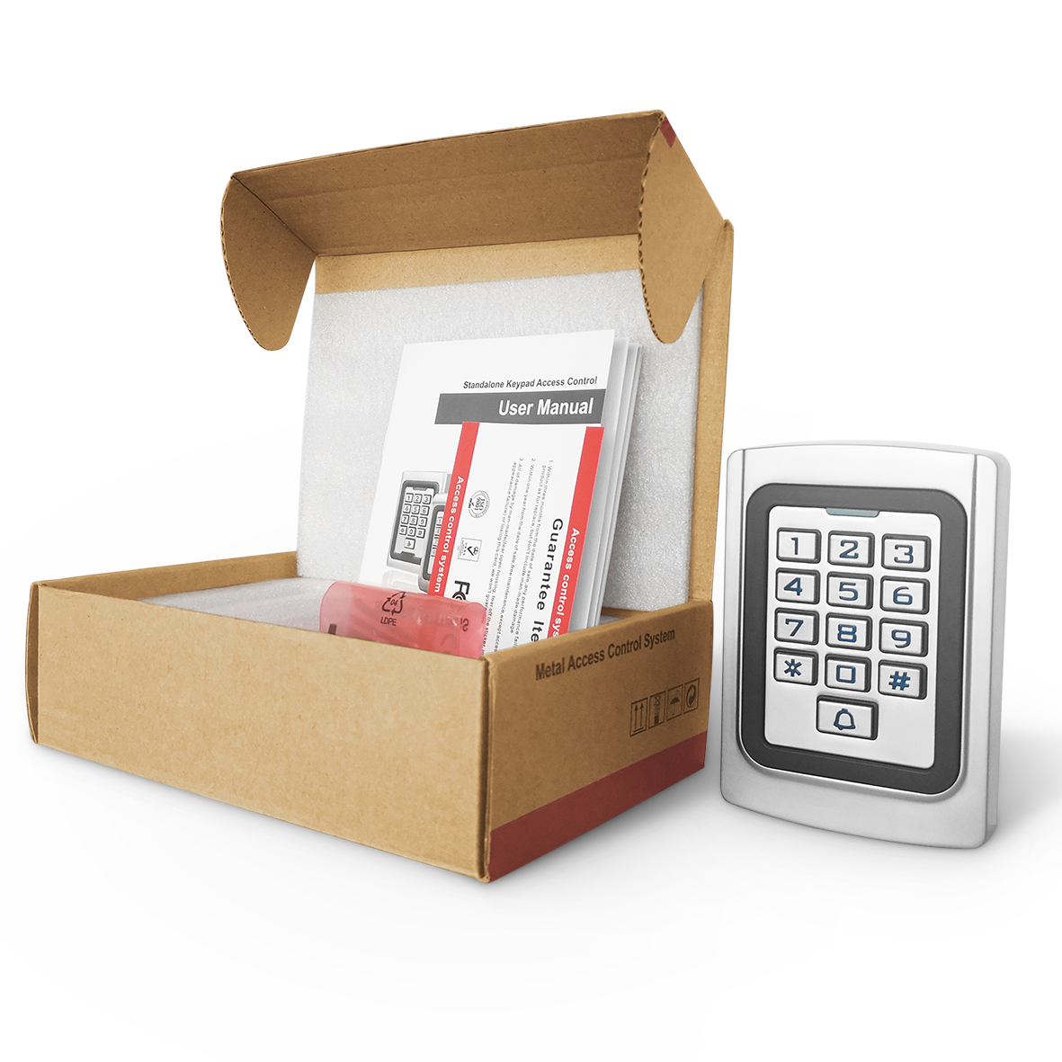
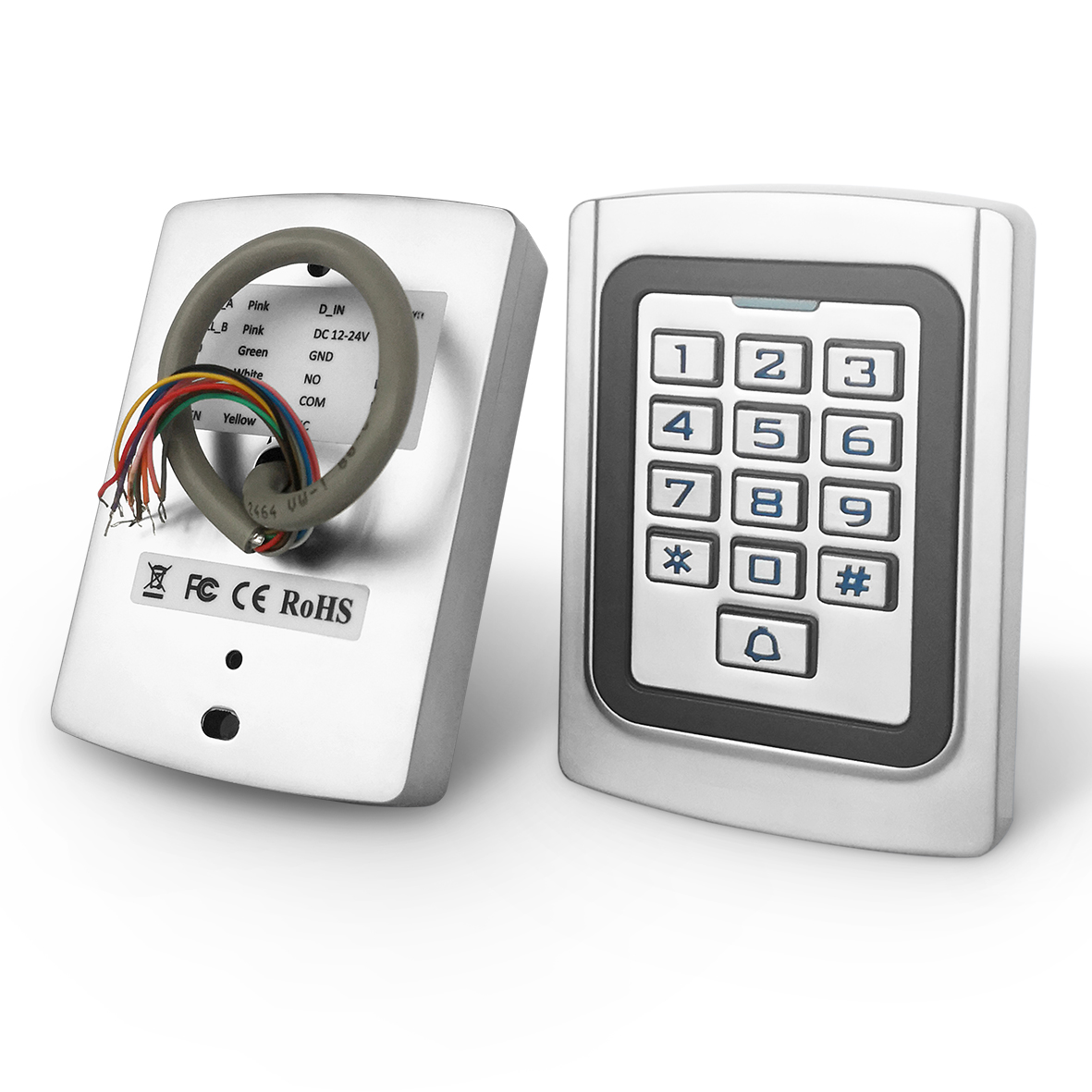
1.Product Description
This standalone card reader one door controller support EM card/Mifare card, and keypad password, It adopts unique metal material design, durable backlit metal keyboard, located in the united states atmel microprocessor, strong anti-interference ability, safety and reliability, powerful functions, easy to use, can be widely used in office buildings, residential and other public place.
2.Specifications
| Voltage | 12-24V DC |
| Distance | Card reading 3-6cm |
| Temperature | -40℃ ~ +60℃ |
| Humidity | 10%~90%RH |
| Active current | ≤30mA |
| User capacity | 1000 users |
| Door unlock time | 1-99s adjustable |
| Lock output load | ≤3A |
| Alarm output | ≤20A |
| Size | 110mm x 75mm x 25mm |
3.Feature
| Feature | Description |
| Low power consumption | Standby current is less than 30mA |
| Weigand output | WG 26 input/output |
| Fast response | Swipe card just less than 0.1s |
| Luminous keyboard | Convenient for night operation |
| Doorbell interface | Support |
| Multiple ways to open doors | Card, password, card+password |
| Independent password | Open the door with a code |
| Modify password | Users can modify the door opening password |
| Delete card | Use the keyboard to delete the card ID after the card is lost |
4.Buzzer And Light Indication
| Operation Status | Indicator | Buzzer |
| Stand by | Red flash | |
| Press keypad | Di | |
| Operation successful | Green | Di |
| Operation failed | DiDiDi | |
| Enter into programming mode | Red | Di |
| In the programming mode | Orange | |
| Exit from the programming mode | Red flash | Di |
| Open the door | Green | Di |
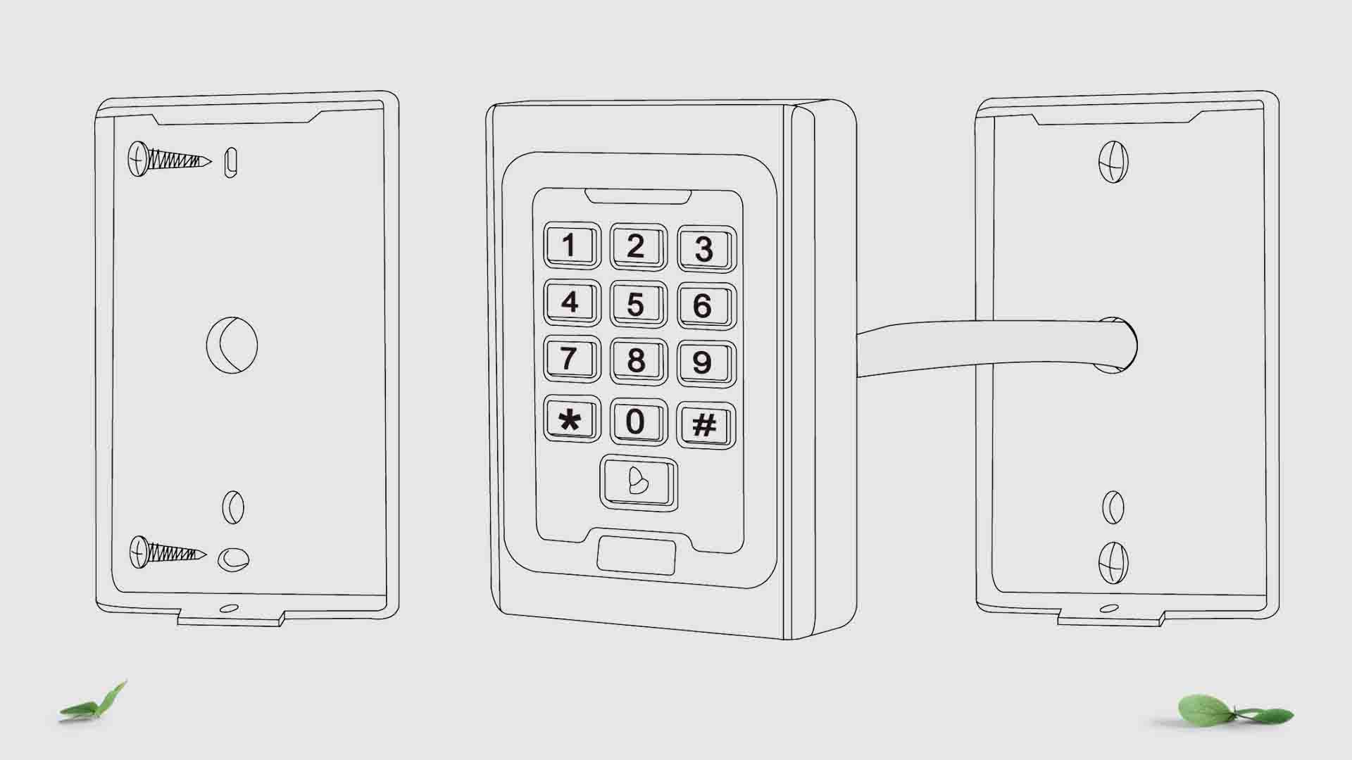
5.Installation
- Remove the back cover from the keypad using the supplied special screw driver.
- Drill 2 holes on the wall for the self tapping screws and I hole for the cable.
- Put the supplied rubber bungs to into the two holes.
- Fix the back cover firmly on the wall with 2 self tapping screws.
- Thread the cable through the cable hole.
- Attach the keypad to the back cover.
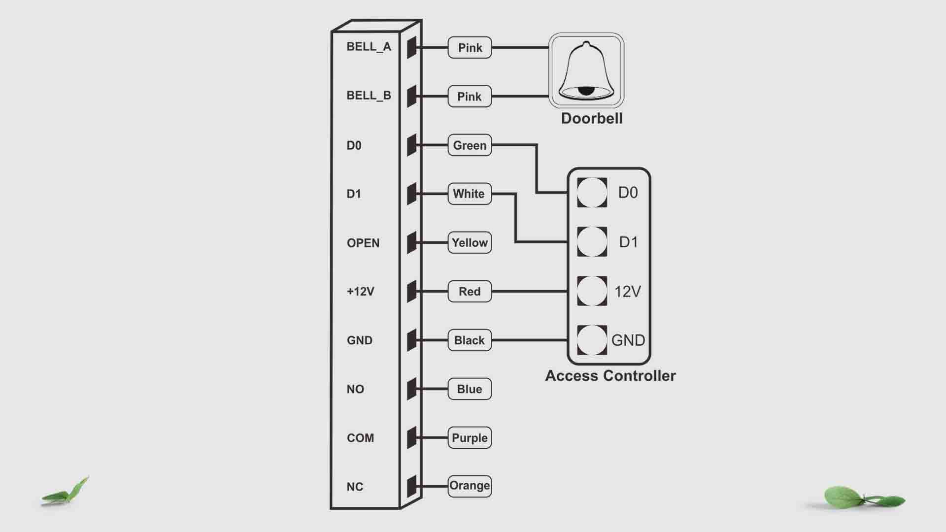
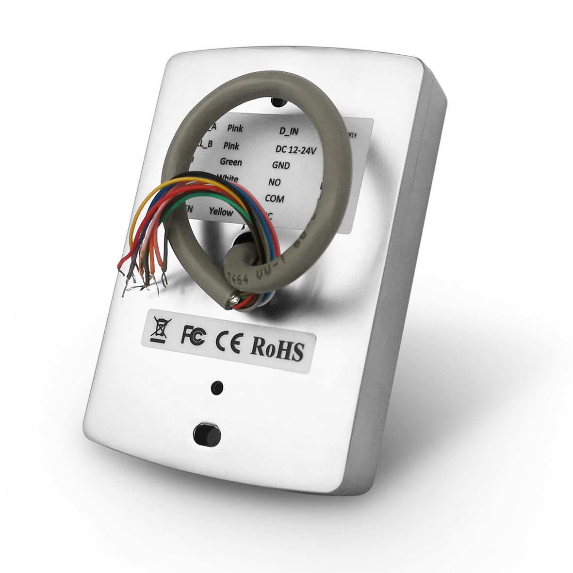
6.Wiring Details
| No | Funtion | Color | Function description |
| 1 | BELL_A | Pink | Doorbell button one end |
| 2 | BELL_B | Pink | Doorbell button to the other end |
| 3 | D0 | Green | WG output D0 |
| 4 | D1 | White | WG output D1 |
| 5 | OPEN | Yellow | Exit button one end(The other end connected GND) |
| 6 | DC12V | Red | 12V + DC regulated power lnput |
| 7 | GND | Black | 12V – DC regulated power Input |
| 8 | NO | Blue | Relay normally-on end |
| 9 | COM | Purple | Relay public end |
| 10 | NC | Orange | Relay closed end |
Warning Remind
- Please do not repair the machine without permission, if there is any problem, please return to the factory for repair.
- If drilling holes before installation, please check the hidden wires or conduits carefully to prevent unnecessary troubles caused by drilling and breaking the hidden wires when drilling,use safety glasses when drilling holes or securing wire clips.
- If the product is upgraded, the instruction manual may be different without prior notice.
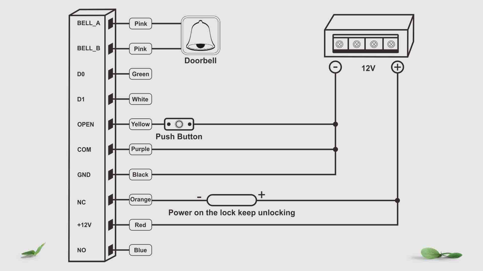
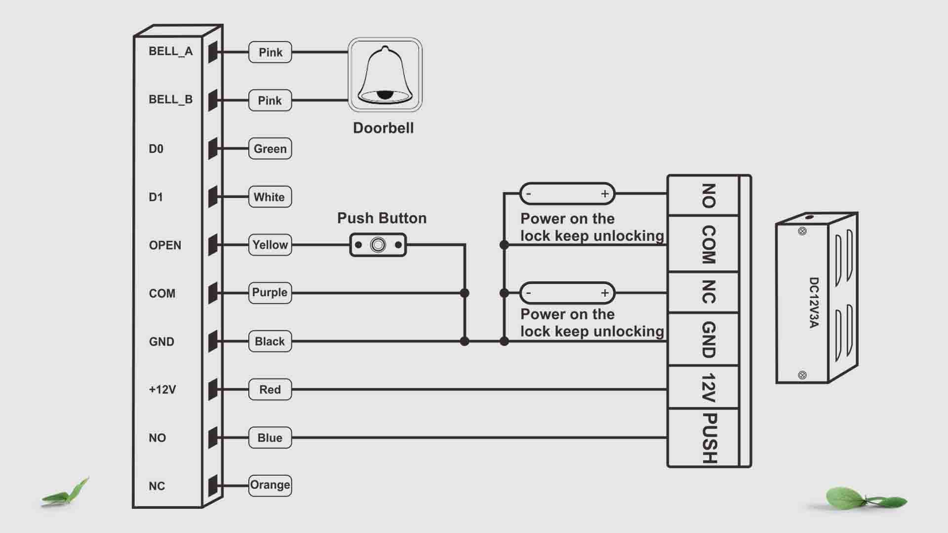
7.Diagram
- Common Power Supply Diagram
- Access Control Power Supply Diagram
- Card Reader Diagram