Description Of The Product
- The FC20-28L20 series safety device is composed of N transmitter units and receiver units, both contained within sturdy aluminum profles. Beams of infrared rays are generated capable of detecting the presence of people and / or objects when interrupted. The communication between the transmitter unit and the receiver unit is carried out optically and, therefore, no electrical connection between the two units is necessary.
- To avoid reflections and / or reception errors, a unique identifcation code is set for each infrared beam. When an object, limb or body of a person interrupts the beam of rays emitted by the transmission unit, the output is immediately opened by the receiver unit, with consequent blocking of the automation. The system is only safe when the TEST system is used, this allows you to check the correct functioning of the barrier .
- Typical applications of the system include detection of people or material obstacles near access gates such as: 1.High-speed folding doors and sectional doors, 2.Sliding doors and gates.
Technical Details
| Working volatage | 12-24VAC/DC |
| Number of beams | 28/32 |
| Derection distance | 15m/590inch |
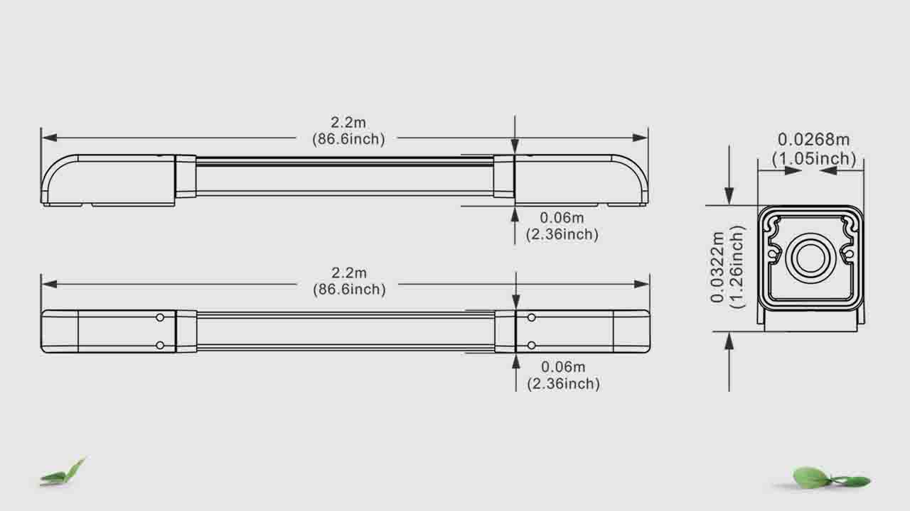
| Height | 2.2m/86.6inch(Optional) |
| Response time | <45ms |
| Safety outputs | Max 350mA@40VDC |
| Max speed door closing | 3m/s |
| Max speed door opening | 3m/s |
| Working temperature | -20℃~+60℃ |
| Humidity | 95%RH In Max(No condensation) |
| IP rating | IP55 |
| Material | Structure: aluminium |
| Cover: polycarbonate | |
| Consumption max @ 10 VDC | RX:3W |
| TX:<3W | |
| Light wavelength | 940nM |
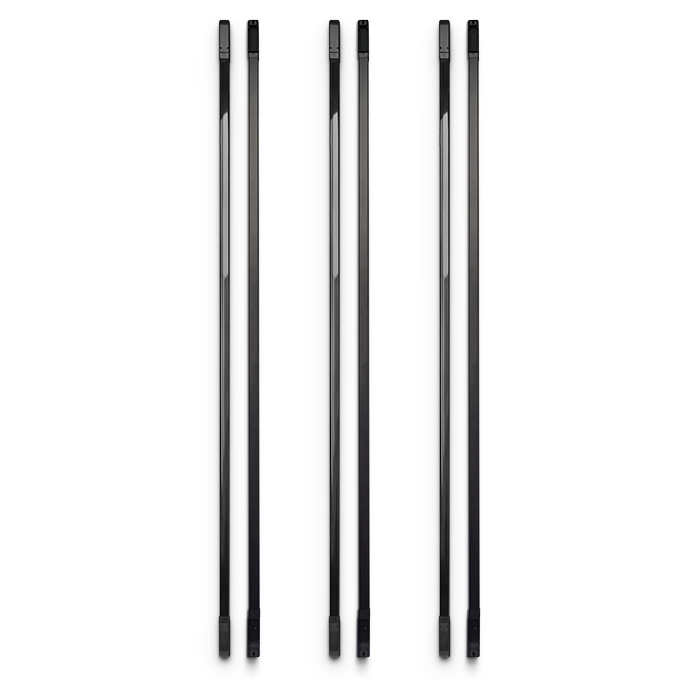
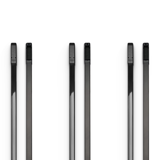
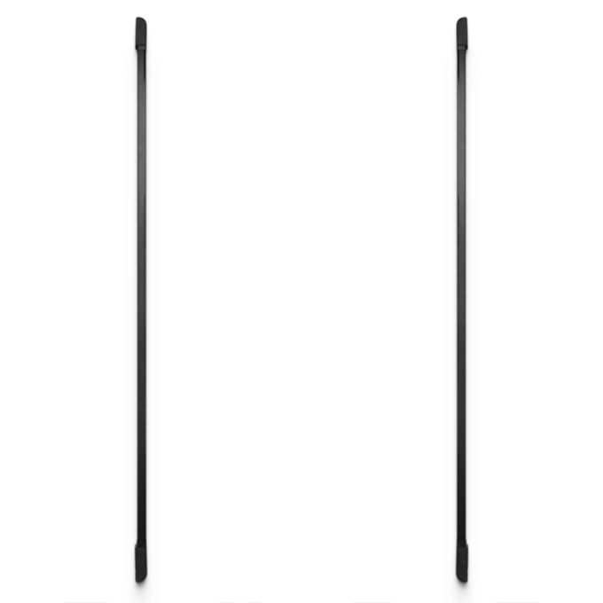
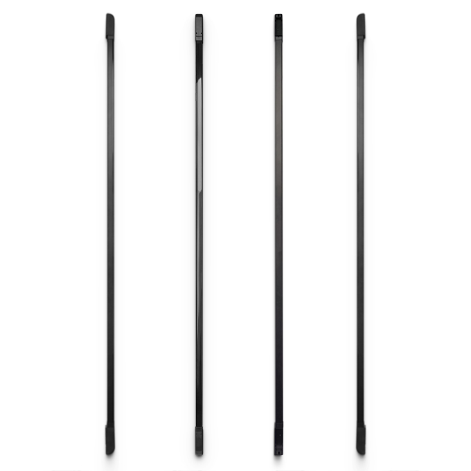
Products Size Photo
Curtain Photocell Installation
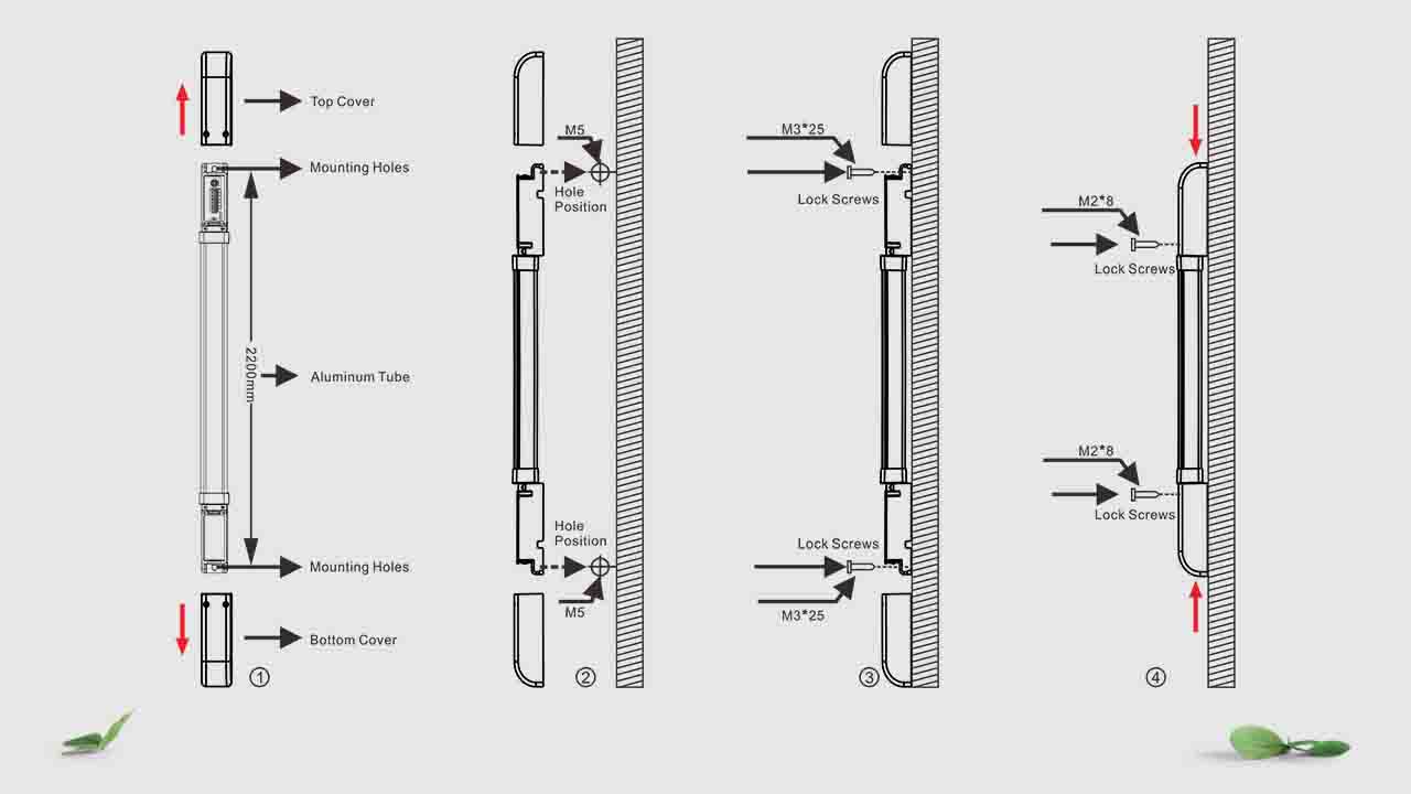
Operation Step
♦ Remove the Top and Bottom Cover,and connect the wires,and lead the thread end from the threaded port.
♦ Confirming the installation position , align the transmitter and receiver in parallel, and mark the hole positions.
♦ Use a percussion drill to drill holes at the location of the wall marking hole, and knock the wall plug into the fixing hole to fix it with screws.
♦ Use M3*25 screws to lock the transmitter and receiver, and connect the power supply to test. If the angle is deviated, you can rotate the aluminum tube for correction. After debugging, lock the rotating screw.
♦ Using M2*8 Screws locked top cover and bottom cover , and testing.
Precautions In The Installation Of The Device
- The outputs (OSSD) of the barrier must be used only as devices for stopping the machine and not as control device.
- The size of the minimum object to be detected must be greater than the space between the beams of the barrier.
- Installations near very intense light sources should be avoided, in particular near the receiver unit.
- The presence in the workplace of smoke, fog or dust can reduce the operating range of the device.
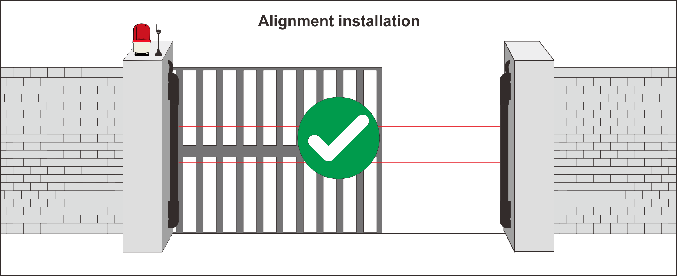
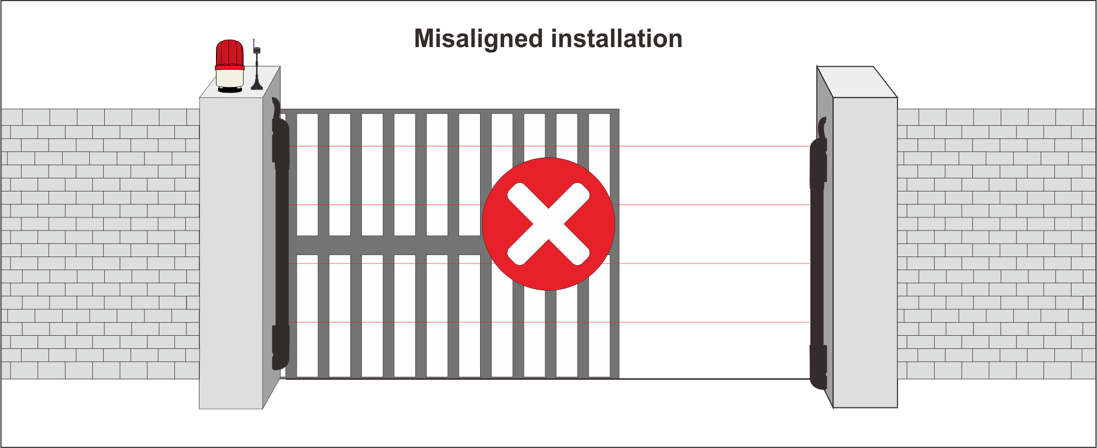
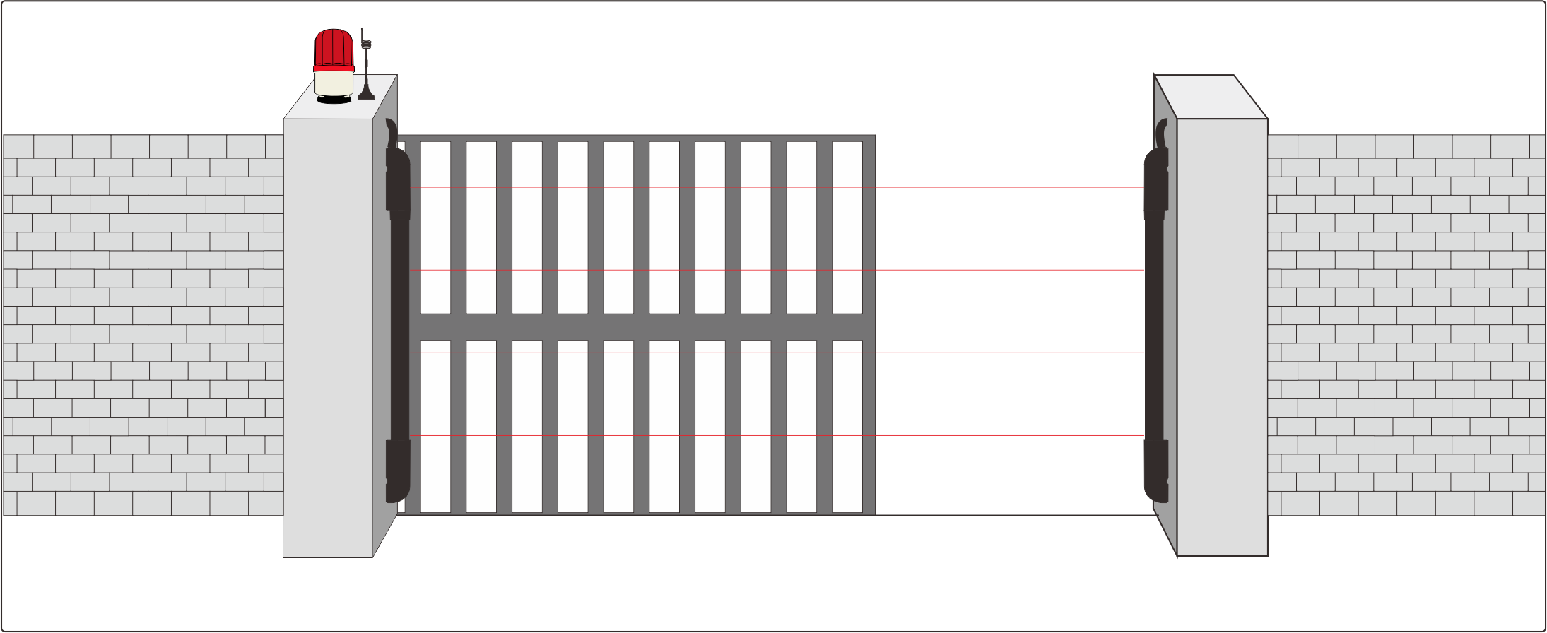
Positioning Of Transmitter And Reiceiver
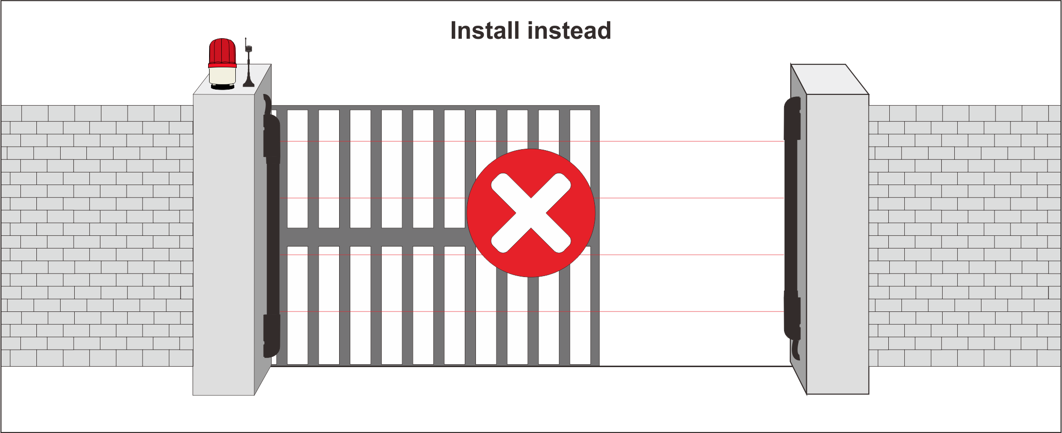
Transmitter and receiver must be installed opposite each other, with the rays positioned orthogonallycompared to the transmission and receiver ray. The below configuration must be avoided:
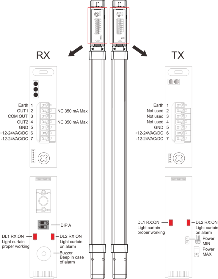
Connection Diagram
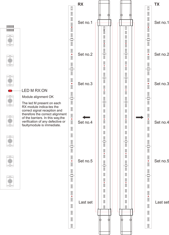
Programming Of The Set
- FC20-28L20 series light curtain is composed of one BASIS set which are connected all other set with 8 rays each.
- The number of set hang on the choose version.
Mode
Set Up Of The Receiver
The FC20-28L20 series barrier creates a detection zone consisting of infrared rays 4.5 cm apart. In case of interruption of the beams, the barrier communicates the alarm status to the control unit, towhich it is connected. When the detection zone returns free, the barrier returns to the rest state.
First set DIP A on the receiver base as follows:
Set up on receiver
| DIP 1A | ON | Mode:Gate |
| OFF | Mode:Door | |
| DIP 2A | ON | Installation on a sectional door (DIP 1 OFF) |
| OFF | Installation on a rapid door (DIP 1 OFF) |
Set Up On Transmitter
There is a 2 (standard version) or 4 (synchro version) ways dip in the basis of the transmitters.
You can see how to programm it:
Set up on trasmitter
| DIP 1B | ON | TEST if terminals 5-6 aren’t powered |
| OFF | TEST if terminals 5-6 are powered | |
| DIP 2B | Not used | |
| DIP 3B | Not used | |
| DIP 4B | Not used | |
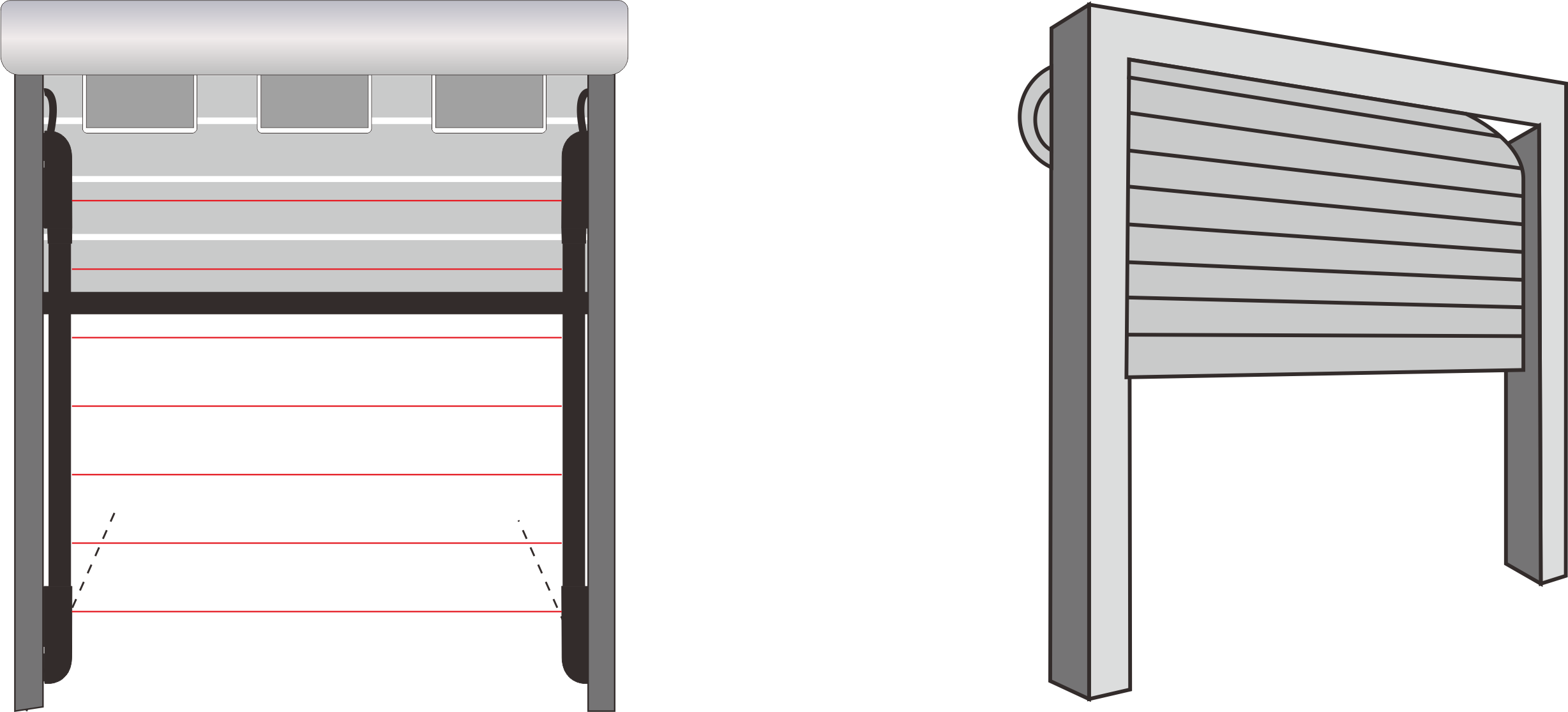
Installation For Door
It is possible to use the FC20-28L20 series barrier, on sectional doors (DIP 2A ON) or rapid doors (DIP 2A OFF), it is necessary to install them out of parallax as shown in the fgure. In this way the barrier recognizes whether the interruption of the infrared rays is due to the passage of a person, the presence of an object or if the door is closed. (Gradual shut down)
Installation For Gate
In the case of installation on sliding gates, DIP 1A must be set to ON. It is recommended to install them on the same side, either internally or externally.
Troubleshooting
To recognize and solve any problem for the light curtain FC20-28L20 series read this table:
| DL1 RX
RED |
DL2 RX RED |
DL1 TX RED |
Resolution |
| Switched off or fx | Switched off or fx | 1.Check the connection and the power supply. 2.If the connections are ok it means that RX (Basis,first set) must be replaces because it is damaged. |
|
| Slow fl ashing | Switch on | Slow flashing | 1.The barrieris in alarm, make sure that the intervention area is clear. 2.Each segment (8 beams) of the RX barrier has a LED which if off indicates the module in alarm. 3.Check the alignment between the barriers. 4.Clean the elements with a soft cloth. 5.If this does not correct the fault, replace the unit. |
| Fast flashing | Check the wiring connection of the light curtain receiver | ||